Short technical articles on machining strategy, CAD/CAM and inspection planning.
CNC Milling4 min read
3+2 axis vs. 5-axis class machining
With 3+2 machining the rotary axes hold a set angle during cutting. Simultaneous five-axis machining can change the tool orientation during the cut.
Tool angle relative to the workpiece
Indexed 3+2The angle stays fixed during the cut.
Simultaneous 5-axisThe angle can change during the cut.
In this example, the swivel rotary table changes the angle. The spindle stays vertical and spins the cutter around its own axis. In indexed 3+2 machining, the table can be tilted before cutting.
Read technical detailsClose
In 3+2 axis machining, the rotary axes bring the part to a set angle and stay locked while cutting; the linear X, Y and Z axes do the cutting motion. Several faces of the part can be reached in one set-up, but the tool approaches each face at a fixed angle.
When is it enough?
For angled holes, inclined faces and pockets on different sides of prismatic parts, 3+2 is usually both sufficient and efficient. Shorter tools can often be used, which benefits rigidity and surface finish.
When is simultaneous motion needed?
Freeform surfaces with constantly changing surface normals, and some deep or narrow features, may require the tool axis to be re-oriented continuously during the cut. This is where simultaneous machining — linear and rotary axes moving together — comes in.
Conclusion
The right approach depends on the part's geometry, tolerances and quantity. The decision should be made as part of the manufacturability review, before CAM programming starts.
Controlling distortion in thin-wall aerospace parts
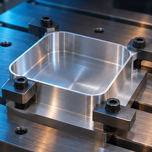
Support thin walls close to the cut and leave stock for a light finishing pass.
Low-profile clamps support the base and keep the thin rim accessible.Read moreClose
Aerospace structural parts often use pockets and thin walls to save weight. When most of the stock is removed, released residual stresses and cutting forces can lead to dimensional deviation.
Sequencing
Removing material evenly from both sides, allowing the part to relax between roughing and finishing, and leaving finishing passes as late as possible are common approaches.
Fixturing
Clamping forces must hold the part without deforming it. The position of supports, the clamping force and the shape the part will take once released are considered together when planning operations.
Toolpaths
Toolpath strategies that apply a constant, controlled chip load to the walls help reduce vibration and wall deflection — so strategic choices in CAM translate directly into part quality.
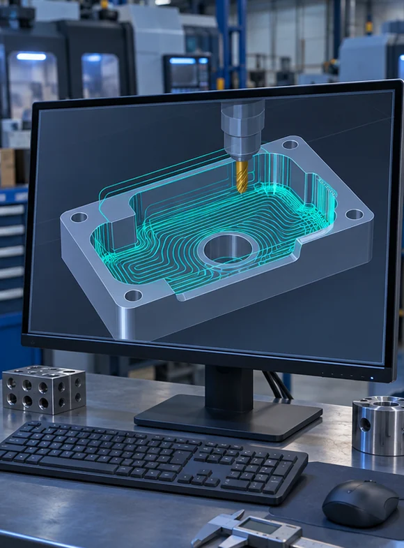
Simulate tool, holder and fixture motion before releasing the NC program.
CAM setup illustrationRead moreClose
In multi-axis machining, the relationship between tool, holder, fixturing and machine components becomes complex. The first time a program runs on the machine is the most expensive moment to discover an error.
What is verified?
Material-removal simulation checks for remaining stock and gouges; machine-kinematics simulation checks axis limits, rotary positions and potential collisions.
Post-processor
Motion in CAM reaches the machine correctly only through a post-processor that matches the machine. Simulating the generated NC code is the most reliable way to confirm consistency between CAM and machine.
The benefit
Verified programs need fewer corrections on the first article, saving both time and material.
From drawing to inspection plan: critical characteristics
Identify critical features and drawing datums before choosing how to measure them.
CMM inspection illustrationRead moreClose
A drawing defines the characteristics that carry the part's function and their permitted variation. The inspection plan defines how those characteristics will be verified during production.
Datum structure
Geometric tolerances are defined relative to the datum structure on the drawing. Aligning fixturing and measurement strategy with that structure is essential for meaningful results.
Method and frequency
For each characteristic, a suitable measurement method, stage (first article, in-process, final) and frequency are defined. Critical characteristics are monitored more often.
Records
Recording results both documents conformity of the part and provides a basis for monitoring process behaviour over time.

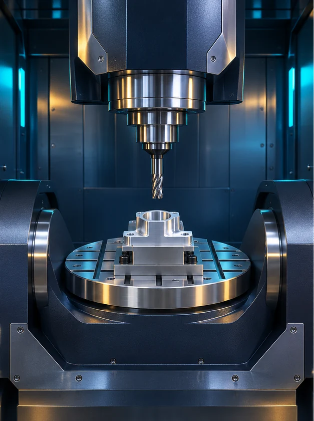 Indexed 3+2The angle stays fixed during the cut.
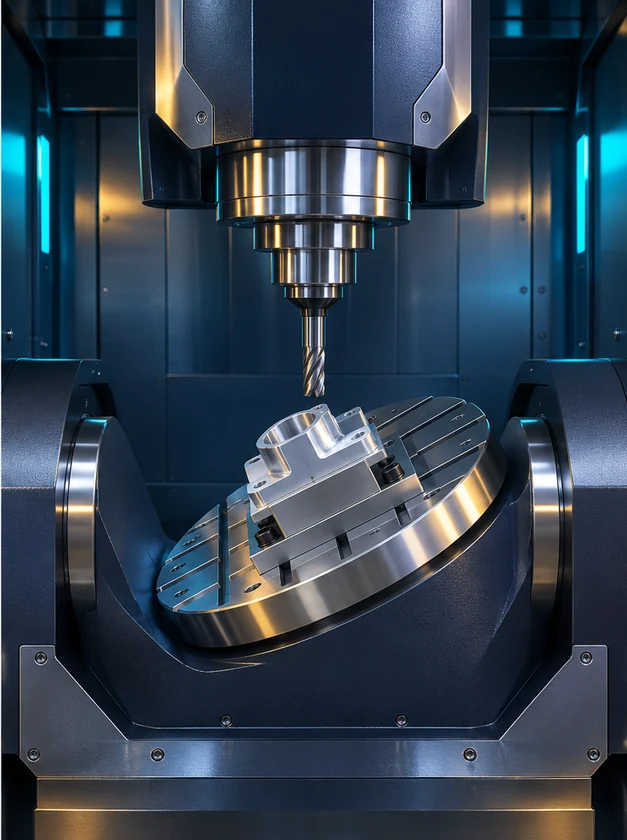 Simultaneous 5-axisThe angle can change during the cut.