Capabilities
CNC machining, CAD/CAM and engineering
Each capability is designed to feed the next. Below you will find the scope of each and the information we need for a quotation.
Download capabilities brochure (PDF)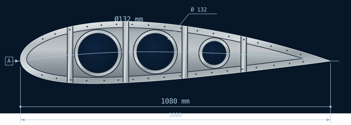
Precision Parts Manufacturing
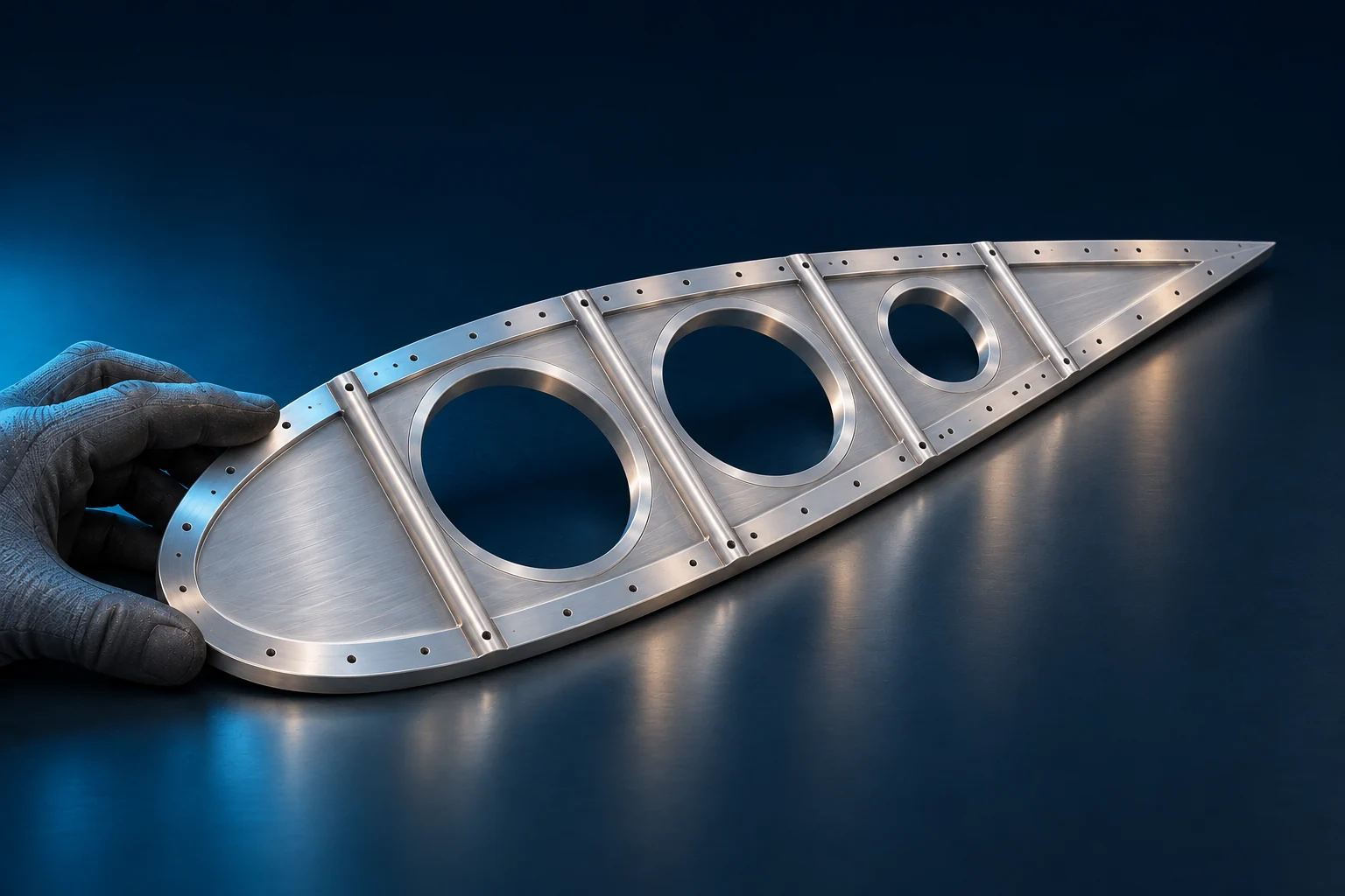
We manufacture parts for the aerospace sector with drawing and tolerance requirements at the centre. Material and geometry review, fixturing and operation planning, CAM programming, machining and inspection are managed as one connected process.
Scope
- Precision parts with prismatic and complex geometry
- Parts combining milling and turning operations
- Prototype and repeat production
- Tolerance-chain awareness for mating parts
Share for a quote
- Drawing (PDF) and 3D model
- Material and any surface treatment
- Quantity / batch size
- Critical characteristics and special requirements
CNC Milling
- Part types
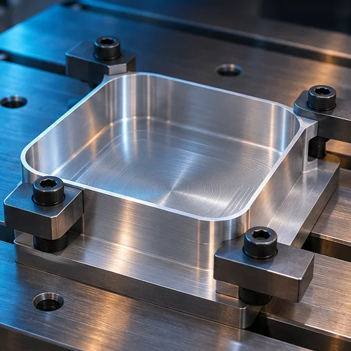
- Pocketed and multi-face parts
- Inputs
- STEP model, drawing, material
- Checks
- Pocket depth and critical faces
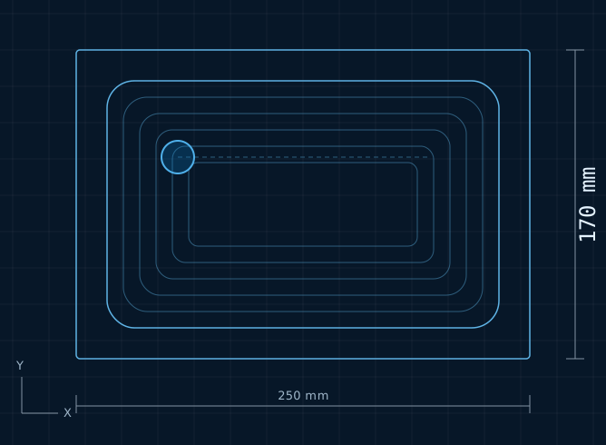
We machine each part on the centre that best suits its geometry. With 3+2 positional machining on our DMX 80 U machines and 5-axis class capability on our DMU monoBLOCK machines, we aim to reach multiple faces of a part in a single set-up. Fewer re-clampings help preserve the relationship between features.
Scope
- Pocketing, contouring, drilling and freeform surfaces
- Single set-up planning for multi-face parts
- Distortion-aware sequencing for thin-wall and pocketed parts
- CAM-based toolpaths and NC programming
Share for a quote
- 3D model (STEP / IGES)
- Drawing and tolerances
- Material and stock details
- Quantity and lead time
Turning
- Part types
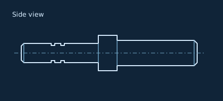
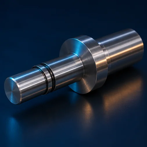
- Shafts, bushings and rotational parts
- Inputs
- Diameters, lengths, material
- Checks
- Diameter, length and drawing tolerances
We turn shafts, bushings, flanges and similar rotational parts to drawing and tolerance requirements. Where a part also needs milling, turning and milling steps are planned within a single operation plan.
Scope
- OD, ID and facing operations
- Grooves and stepped profiles
- Parts combined with milling operations
- Fixturing planned to protect concentricity and run-out
Share for a quote
- Drawing (PDF)
- Material and stock size
- Quantity
- Critical diameters and tolerances
CAD/CAM
- Part types
- Complex and multi-face geometries
- Inputs
- 3D model, drawing, revision
- Checks
- Tool access and simulation
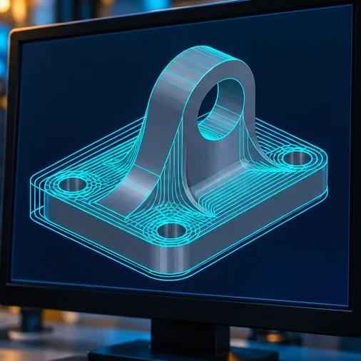
Part quality starts at the design and programming desk. We prepare 3D models for production, choose toolpath strategies to suit the geometry and material, and verify programs by simulation before they reach the machine.
Scope
- 3D part and assembly modelling
- Toolpath strategy and tool selection
- Simulation and collision checking
- Machine-specific NC programs
Share for a quote
- Existing 3D model or drawing
- Revision status
- Critical surfaces and dimensions
Mechanical Engineering
We decide how a part will be made before it is made. We review designs for manufacturability, prepare or revise drawings where needed, and plan fixturing and operation sequence.
Scope
- Design for manufacturability (DFM) review
- Drawing preparation and revision
- Fixturing and operation planning
- Design improvement suggestions
Share for a quote
- Design data and intended use
- Assembly relationships
- Expected quantity and cost target

Metrology & Quality Control
We inspect the parts we produce against the dimensions and tolerances on the drawing. Critical characteristics are defined at quotation stage and verified on the first article, in process and before delivery. Inspection records are shared on request.
Scope
- Dimensional inspection to drawing
- First-article inspection
- In-process checks
- Inspection records on request
Share for a quote
- Drawing and critical characteristics
- Required document / report type
Request for Quotation
Send us your drawing. We'll plan the rest together.
Let us prepare a manufacturability review and quotation for your project. You can securely upload PDF, STEP, IGES, DXF or ZIP files through the form.
- For a faster quote
- 01Drawing (PDF) and 3D model (STEP)
- 02Material and surface treatment
- 03Quantity and batch size
- 04Required delivery date
Sample bracket study
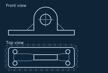
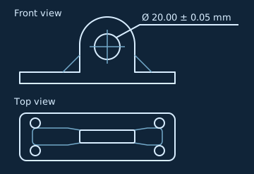
Illustrative bracket. The bore callout follows the same feature from the drawing to CAM and dimensional inspection.
CAM step: rough and finish the bore with a toolpath selected for access and geometry.