
Precision Machining · Engineering · Quality
Home/Quality

Quality Control

Measuring the right surface, with a suitable method, against technical requirements.

Right measurement, right decision

Right Surface

Measuring on the functional surface.

Right Method

Suitable instrument and probe per feature.

On Record

Results are kept traceable.

Measurement Planning

Measurement is planned before production

Critical characteristics on the drawing are identified before work starts, and a method, equipment and frequency are defined for each one.

  1. 01Drawing and requirement review
  2. 02Identifying critical characteristics
  3. 03Selecting method, probe and equipment
  4. 04Inspection plan and frequency
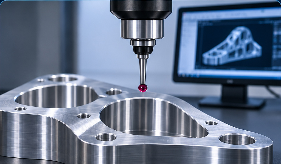
CMM probe in contact with the top reference surface of a part
CMM Principles

How coordinate measurement works

A coordinate measuring machine (CMM) records the coordinates of the points where its stylus touches the part and fits geometric elements such as planes, circles and cylinders to them. The part is first aligned to the drawing datums, and every result is evaluated in that coordinate system.

In the image, the stylus tip is touching the top reference surface of the part; points like this are used to establish planes and datums.

  • Datum alignment and coordinate system
  • Probe and stylus suited to the feature
  • Enough, well-distributed measurement points
Bore Scanning & Measurement

Contact on the inner wall

When measuring a bore, the stylus tip contacts the inner cylindrical wall. A few points may be enough for diameter; form characteristics such as roundness and cylindricity are evaluated with many points or continuous scanning, at two or more depths in the bore.

  • Diameter and position: evaluated relative to the datums
  • Roundness: evaluated in each cross-section
  • Cylindricity: sections evaluated together
CMM probe head Stylus and ball tip Part section Scan 1Upper depth Scan 2Lower depth Contact point: the inner cylindrical wall of the bore
Geometric Tolerances

Form, orientation and location, not only size

Geometric dimensioning and tolerancing (GD&T) defines a feature’s form, orientation and location as well as its size. The tolerances we meet most often:

Position

How far a feature, such as a hole axis, may deviate from its true position relative to the datums.

Flatness

The zone between two parallel planes within which a surface must lie.

Roundness

Each cross-section must lie between two concentric circles.

Cylindricity

The whole cylindrical surface must lie between two coaxial cylinders.

Perpendicularity

The 90° orientation of a surface or axis relative to a datum.

Parallelism

A surface or axis must stay parallel to a datum.

Datums & Reference Surfaces

Every measurement has a reference

The datum letters in a feature control frame state which surfaces the measurement refers to, and in which order. The primary datum locates the part on three points, the secondary on two and the tertiary on one. Using the same datum order in machining and inspection keeps results comparable.

Technical note: datums and reference surfaces →

Ø 0.05ABC CharacteristicTolerance zoneDatum references Illustrative example.
Quality Through Production

Quality at every step

01

Inspection Plan

Critical features and methods are defined before work starts.

02

First Article Check

The first part is verified on all critical dimensions.

03

In-Process Check

Measurements are taken at defined intervals during production.

04

Final Inspection

Final verification and records before delivery.

Inspection Records

What is measured is recorded

Inspection results are stored against the part and the order, so it is possible to trace when a characteristic was checked, how, and with what result.

01

Inspection plan

Critical characteristics, methods and frequency.

02

First-article record

Results for every critical dimension on the first part.

03

In-process records

Measurements taken at defined intervals during production.

04

Final inspection report

Results of the last verification before delivery.

Quality Policy

Quality lives in the details

Our approach to quality is built on correct planning, correct measurement and open communication.

01

Full conformance to technical requirements

Drawings and customer requirements are the reference for every job.

02

Zero-defect goal

We aim to identify and address risks before production.

03

On-time delivery

We set realistic schedules and share status openly.

Continuous Improvement

Learning from every part

We use measurement results not only for accept/reject but to improve the process. Recurring deviations feed back into the machining plan.

  • Root-cause analysis of deviations
  • Corrective action tracking

Have a custom project?

Let us review your drawings and requirements and plan the right manufacturing approach together.

Request a Quote →